Kantronics D4-10 Transceiver Alignment Procedure
Introduction
The Kantronics D4-10 data radio is very easy to align with the proper
equipment. This procedure encompasses instructions provided in the D4-10
Operator's Manual along with information documented by other sources1 and personally gained knowledge.
Required Equipment
- Digital Multimeter (DMM)
- Oscilloscope
- Service Monitor
- SINAD Meter
- RF Watt Meter
- RF Dummy Load able to absorb greater than 10-Watts at the UHF level
VCO Alignment
The following steps will properly set the VCO PLL "lock" voltage to allow
rapid switching between receive and transmit.
Procedure
- Attach the DMM positive probe to the rear pin of test point JP2, ground
reference is on the front pin. Set the DMM resolution to 0.1mV DC.
- Attach the dummy load to the watt meter, and the watt meter to the
antenna jack.
- Apply power to the radio, set the channel selector to channel-1, wait
10 minutes for the crystal heaters to warm up if installed, and observe the voltage
level of the VCO on the oscilloscope with the radio in the receive mode.
Set the voltage to 2.500 volts DC by adjusting potentiometer RXA1.
- Key the radio using the PTT pin on the analog I/O port, causing
the radio to transmit. Observe the watt meter and the transmit LED on the
front of the radio to verify a positive reading and illumination. Observe
the voltage reading on the DMM, and set to 2.500 volts DC by
adjusting potentiometer TXA1. If the transmit LED does not illuminate,
then the oscillator is not operating which can be corrected by adjusting
the slug in inductor TL1.
- Key and unkey the radio several times, observing the DMM in
the process. The voltage should remain steady at 2.500 +/-0.01 volts DC in both the
receive and transmit modes. With the voltage being equal in both modes,
fast transmit/receive switching is possible.
- Repeat the same steps for channel-2 if populated with channel
crystals.
Transmitter Alignment
Procedure
- Key the radio using the PTT pin on the analog I/O port, causing
the radio to transmit. Adjust the transmit VCO trimmer coil TL1 (TL2 for channel-2) to
bring the transmitter exactly on frequency.
- Key the radio using the PTT pin on the TTL I/O port. The frequency
should now be 10-KHz lower (bit value=0) than in step 1. If not then adjust R11 to
cause a 10-KHz shift. To check the high side shift, apply 5.0 volts DC
(available from the output of VR1) to pin 1 on the TTL I/O port. The frequency
should shift 10-KHz above (bit value=1) the center frequency set in step 1 .
- It is important that there is at least 10-KHz of shift both down and up
from the transmitter center frequency. If the shift is too narrow, then
performance falls off drastically. Another acceptable parameter is to have
between 19.200-KHz and 20.000-KHz of total bandwidth (e.g. 433.4200-MHz
to 433.4392-MHz).
Receiver Alignment
Procedure
- Establish the following test equipment and radio configurations in
preparation for receiver alignment.
- Set the signal generator to the receive frequency, configured to apply a 1-KHz
modulated FM signal with 5-kHz deviation and 2 to 3 microvolts of RF output.
Connect the generator to the D4-10's antenna jack.
- Connect the oscilloscope probe to the RXData circuit (pin 5) on the
TTL I/O port. Configure the oscilloscope to handle a 1-kHz waveform
(time/division: 0.5-milliseconds), DC coupled at 5.0 volts/division,
with the vertical trigger source tied to the probe channel.
- Connect the SINAD meter across a 8-ohm speaker
that is connected to the 3.5mm audio output jack. Connect the second oscilloscope
probe to the audio output as was done with the SINAD meter. Adjust the audio
output to a comfortable level. This provides good visible and audible clarity.
- Set the D4-10's bandwidth selector to the narrow position.
- With signal applied to the D4-10, adjust the receiver VCO trimmer coil RL1 (RL2 for channel-2)
for the best quieting level on the SINAD meter. The objective is to get
the receiver close to the desired receive frequency.
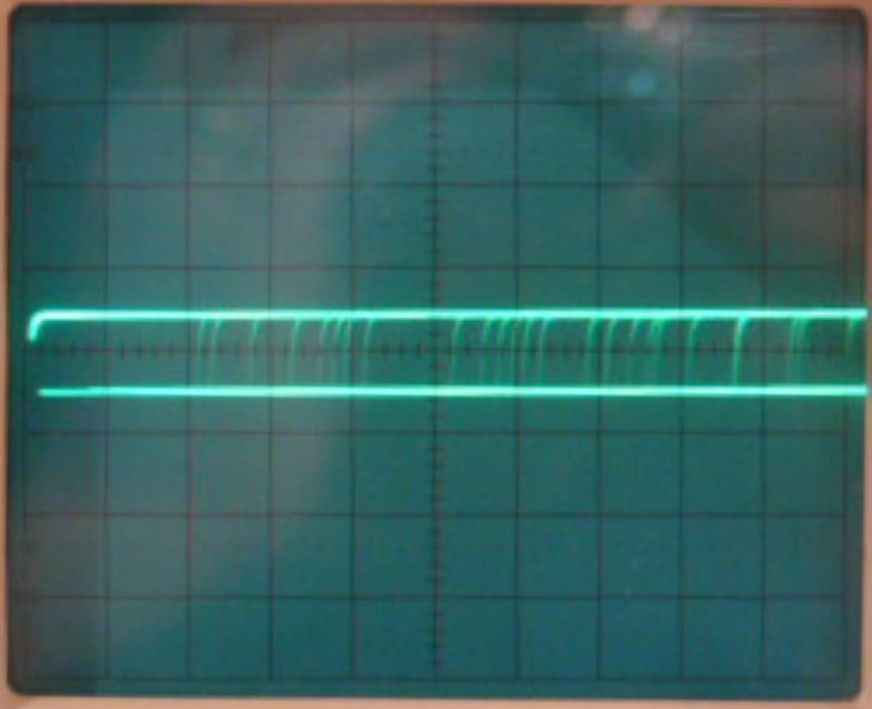
- Disable signal generation into the D4-10 and observe the TTL RXData
circuit on the oscilloscope. Two horizontal lines should be visible,
representing logic zero and one with noise in between them. One line may
have a greater intensity than the other, or one line may even be missing,
both conditions indicating an imbalance between logic zero and one.
Adjust the data slicer threshold potentiometer R17 to produce an equal
amount of intensity on both lines which will put the data slicer in the
center of the noise passband. Figure-1 illustrates a properly adjusted
data slicer threshold.
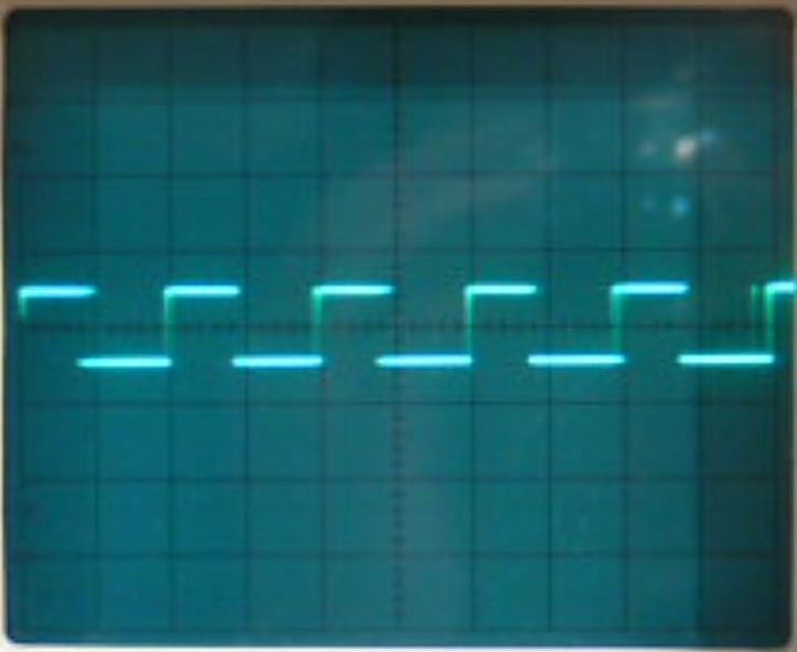
- Apply signal generation to the radio, reducing the deviation to
approximately 3-kHz and making certain that the signal is fairly strong
(e.g. 100 microvolts). Set the D4-10 bandwidth selector to wide. A square
waveform should now appear on the oscilloscope. Adjust the VCO receiver
trimmer coil RL1 (RL2 if aligning channel-2) for an equal duty cycle, in
effect the lower and upper edges of the waveform should be the same
width. Figure-2 illustrates the data slicer output with a properly
aligned VCO receiver trimmer coil.
Figure-2: Data slicer output with properly aligned VCO receiver
trimmer coil
Alignment Procedure Completed
Footnotes
- "Packet Radio at 19.2kB: Care and Feeding of the Kantronics
D4-10 Radio (Updated 28 October 1996)", John Ackermann, 1996
Original: November 26, 2007 by D.Warner, KA7IJK
Updated: June 19, 2011 by D.Warner, W7SZS

